
Usando somente 3 pinos do Arduino você consegue ter muitas saídas, usando o 74HC595 que é relativamente barato , eu paguei R$ 2,60.
Ele seria um conversor de serial para paralelo , ou seja , você entra com dados serialmente e ele joga para suas saídas de 8 pinos e salva elas até você querer mudar seus valores.

Se quiser ter 16 saídas , basta ligar 2 deles , usando o pino QH' no pino DS , como mostrado aqui nessa figura :

Precisa de mais saídas usando só 3 pinos do arduíno ?
Vai ligando em série, sempre ligar o QH' no pino DS do próximo.

O Código do arduíno é bem simples (usando 2 para 16 saídas) :
https://lastminuteengineers.com/74hc595-shift-register-arduino-tutorial/
https://www.arduino.cc/en/tutorial/ShiftOut
Ele seria um conversor de serial para paralelo , ou seja , você entra com dados serialmente e ele joga para suas saídas de 8 pinos e salva elas até você querer mudar seus valores.

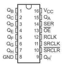
| Pin name | Functions |
|---|---|
| QA-QH | Outputs Q0 (QA) to Q7 (QH). |
| QH' | Serial data output. |
| SER | Serial data input. |
| SRCLK | Serial data input clock. |
| RCLK | Output register (Latch) clock. |
| SRCLR | Active low, Asynchronous Shift register Clear. |
| OE | Active low, Output Enable. |
| VCC | Positive Power Supply. |
| GND | Negative Power supply (Ground - 0V). |
Se quiser ter 16 saídas , basta ligar 2 deles , usando o pino QH' no pino DS , como mostrado aqui nessa figura :
Precisa de mais saídas usando só 3 pinos do arduíno ?
Vai ligando em série, sempre ligar o QH' no pino DS do próximo.
O Código do arduíno é bem simples (usando 2 para 16 saídas) :
int RCLKPin = 3;   // pin 12 on the 74hc595 latch - nSS
int SRCLKPin = 6;  // pin 11 on the 74hc595 shift register clock - SCK
int SERPin = 4;    // pin 14 on the 74hc595 data - MOSI
unsigned int d;    // Data to be sent to the shift reg.
int dir =0;        // Direction of walking 1.

void setup() {
  Serial.begin(9600);          // start serial port (debug).

  pinMode(RCLKPin, OUTPUT);    // Set 595 control PIN sto output.
  pinMode(SRCLKPin, OUTPUT);
  pinMode(SERPin, OUTPUT);

  Serial.println("74HC595 Demo 2xchips for 16 bit register.");

  d=1;
}

void loop() {

    delay(100);
    digitalWrite(RCLKPin, LOW);
    //shiftOut(SERPin, SRCLKPin, (0xff00 & d)>>24); // Se usar 4
    //shiftOut(SERPin, SRCLKPin, (0x00ff & d)>>16);

shiftOut(SERPin, SRCLKPin, (0xff00 & d)>>8); //SEMPRE o MSB primeiro
    shiftOut(SERPin, SRCLKPin, 0x00ff & d);
    digitalWrite(RCLKPin, HIGH);

    if (!dir) d<<=1; else d>>=1; // Shift

    if (d&0x8000) dir=1;           // Set direction.
    if (d&0x0001) dir=0;
}
// the heart of the program
void shiftOut(int myDataPin, int myClockPin, byte myDataOut) {
  // This shifts 8 bits out MSB first,
  //on the rising edge of the clock,
  //clock idles low

  //internal function setup
  int i=0;
  int pinState;
  pinMode(myClockPin, OUTPUT);
  pinMode(myDataPin, OUTPUT);

  //clear everything out just in case to
  //prepare shift register for bit shifting
  digitalWrite(myDataPin, 0);
  digitalWrite(myClockPin, 0);

  //for each bit in the byte myDataOut�
  //NOTICE THAT WE ARE COUNTING DOWN in our for loop
  //This means that 000001 or "1" will go through such
  //that it will be pin Q0 that lights.
  for (i=7; i>=0; i--)  {
    digitalWrite(myClockPin, 0);

    //if the value passed to myDataOut and a bitmask result
    // true then... so if we are at i=6 and our value is
    // %11010100 it would the code compares it to %01000000
    // and proceeds to set pinState to 1.
    if ( myDataOut & (1<<i) ) {
      pinState= 1;
    }
    else {
      pinState= 0;
    }

    //Sets the pin to HIGH or LOW depending on pinState
    digitalWrite(myDataPin, pinState);
    //register shifts bits on upstroke of clock pin
    digitalWrite(myClockPin, 1);
    //zero the data pin after shift to prevent bleed through
    digitalWrite(myDataPin, 0);
  }

  //stop shifting
  digitalWrite(myClockPin, 0);
}
Se for usar as saídas para ligar leds , use um resistor para cada saída de 470 ohms.
Referencias :https://lastminuteengineers.com/74hc595-shift-register-arduino-tutorial/
https://www.arduino.cc/en/tutorial/ShiftOut
Nenhum comentário:
Postar um comentário